PAT Design Principles | by KLK
KLK NEWS
“Resistive design for earthing has become a necessity with increasing weight and importance”.
Therefore from KLK Electro materials we have decided to write this article of general concepts to help clarify any doubts from the hand of our engineering manager in the department of power resistors Fernando Rodriguez Fernandez.
1. DESCRIPTION:
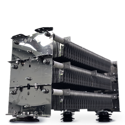
Neutral earthing resistors are devices designed to limit the earth fault resulting from a short-circuit in the primary of a transformer (generally in the distribution or generation area).
These devices are connected to the neutral of the transformer secondary because, in the event of a short-circuit between phases of the primary (or between phase and earth), the line voltages will not cancel in the transformer neutral, giving rise to a voltage and a current associated with it, which, in the worst case, will reach the order of kA, causing a serious danger to people and equipment.
2. FUNDAMENTALS OF CALCULUS:
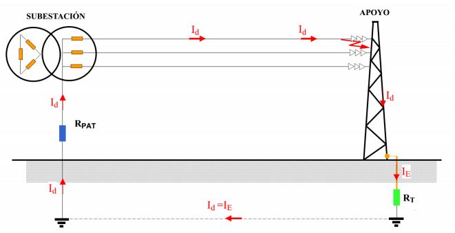
The RPATs are designed considering the worst case scenario, i.e. an earth fault at the generator terminals (considering that the value of the fault resistor RT in the figure is 0).

![]() Imagen cedida por D.Ricardo Granizo | UPM
Imagen cedida por D.Ricardo Granizo | UPM
In this case, the fault current shall be: ?? = ? · ?? /√3 · ????
Where:
Id: earth fault current
c: overvoltage factor
Un: nominal voltage of the network
RPAT: ohmic value of the earthing resistance
In most calculations the overvoltage factor is considered to be 1, although some companies (following the UNE-EN 60909-0 standard) use 1.1.
At present, the only relevant standard for the design of Earthing Resistors is IEEE C52.37, in which critical design values are indicated:
- Average temperature increase for services less than 10 minutes: 760°C
- Maximum temperature increase for services longer than 10 minutes (continuous service): 385°C
3. DESIGN PRINCIPLES:
a. Fundamental aspects of design
The main parameters defining an earthing resistance are as follows:
- Nominal mains voltage
- Earth fault current
- Duration of the defect (extinguishing time)
- Permanent intensity
Of these, the duration of the fault has usually been set at 10 seconds, although the trip time of the protections may be shorter, as it is sometimes necessary to take into account possible consecutive faults.
The intensity of the earth fault is extremely variable as it depends on the capacity of the earth network to absorb the fault, the most common values range from 10 A (usually used for generators, as currents higher than 14 A can damage the stator) to 2000 A. The most common values used by electricity companies are 300, 500 and 1000 A, with values of less than 200 A not being recommended. It is necessary not to lose sight of the fact that this design is the worst possible scenario, with the measured values of earth faults being considerably lower (between 40 and 60%, given that the range of faults that can occur is very varied, and the distance of the fault from the substation can be relevant).
The permanent current to be withstood is given by an unbalance in the network which produces a permanent zero sequence current through the neutral. These unbalances depend entirely on the network and can vary considerably from one country to another (between 25 and 75 A in extreme cases). In the particular case of Spain, a value higher than 25 A is not recommended as it makes no sense given the quality of the grid, and it is important that this value is less than 10% of the fault current assigned to the equipment for economic reasons.

b. Fundamental aspects of design
In addition, there are several aspects that may be relevant to take into account in the design:
- Degree of protection (IP)
- Installation of ancillary elements o Current transformer
- Current transformer
- Disconnector (normal or motorised)
- Equipment enclosure finish according to pollution degree o Galvanised steel painted according to ISO 12944
- Stainless steel (AISI-304) unpainted
- Stainless steel (AISI-316) unpainted
- Cable entry and exit connections o Bulkheads (external connection)
- Isolators (internal connection)
Of all of them, the IP rating is the most controversial, as outdoor equipment in electricity usually has high values (55, 56, 65, etc.). However, RPATs have two peculiarities: the first is that, for construction reasons, their leakage line is very high (over 31 mm/KV), so that pollution does not pose an operating problem; and the second is that this equipment is designed for temperatures of 760ºC, and the heat generated inside must be evacuated. For all these reasons, it is understood that the grade that provides the best compromise between functionality and protection is IP23, and this grade is the most widespread among the electrical companies in our country (ENEL, Iberdrola, EDP…).
KLK Electro materiales slu
Mail | Web | Teléfono | Chatbot | Social Media
Need help?


