Complete Guide to Grounding: Concepts, Importance, and Regulations
Grounding in Electrical Installation
Grounding in Electrical Installations is a critical component in any electrical installation, essential for the safety and efficient operation of electrical systems. Equipotential bonding ensures that all exposed conductive metal parts in an installation have the same electrical potential, significantly reducing the risk of electric shocks.
In this post, we will break down what grounding is, its importance, the applicable regulations, and how to perform an accurate calculation.
At KLK Electro Materiales, we consider it essential that electrical materials companies in Spain take the lead in educating about the importance of proper grounding. Our commitment is to provide training and personalized advice to ensure safe and efficient installations.
Daniel Rendueles CMO KLK Electro materiales
Definition and Key Concepts
Grounding involves connecting the metal parts of an electrical installation to the ground. This process creates a low-resistance path that allows for the safe dissipation of unwanted electrical currents. Its primary objective is to protect both people and electrical equipment.
Main Components:
- Ground Conductors
- Grounding Electrodes or Rods
- Mechanical Connections (Ground Clamps)
- Ground Plates

Grounding Connections Components | KLK electro materials
Importance of Grounding
Personal Protection
It prevents accidental electric shocks by diverting leakage current to the ground, keeping the electrical installation safe.
Equipment Protection
It stabilizes voltage and protects electrical equipment against surges, significantly improving business outcomes.
System Stability
It contributes to the operational stability of electrical systems by keeping safety and productivity fully aligned.
Regulatory Standards
It is essential to comply with the electrical safety regulations set by the electrotechnical standards.
Relevant Standards and Regulations
In Spain, the Low Voltage Electrotechnical Regulation (RBT) is the regulatory framework that governs electrical installations, ensuring they meet the highest safety and efficiency standards. Within the RBT, the Complementary Technical Instruction ITC-BT-18 specifically addresses grounding installations. This ITC establishes the minimum requirements for protection through grounding in low-voltage installations, including the conditions that protection conductors must meet, the permitted grounding system configurations, and the characteristics of the materials to be used.
Additionally, ITC-BT-24 focuses on general prescriptions for protection against indirect contact, including grounding as a fundamental measure to prevent electrical risks. These regulations are mandatory to ensure the safety of people and equipment and play a crucial role in the stability and efficiency of electrical installations.
Complying with these regulations is not just a matter of legality but of professional responsibility, ensuring that every electrical installation operates safely and efficiently in the long term.
“Complying with grounding regulations is not just an obligation; it is a guarantee of safety and efficiency in all electrical installations.”
Rene Abad Commercial Manager KLK Electro materiales
Keys RBT for Grounding in Electrical Installations:
Soil Evaluation: The soil resistivity must be measured to properly design the grounding system.
Material Selection: Use of materials such as copper and galvanized steel that are resistant to corrosion.
Maintenance: Designs that allow for regular maintenance to ensure the system’s functionality.
International Standards (IEC, IEEE):
In addition to the RBT, there are international standards such as those from the IEC (International Electrotechnical Commission) and IEEE (Institute of Electrical and Electronics Engineers) that provide additional guidelines for grounding in electrical installations.


Grounding Calculation
A well-calculated grounding system not only protects against electric shocks but also contributes to the overall stability of the electrical system. To achieve this, it is important to follow a series of steps, ranging from soil evaluation to the final verification of the system.
The accuracy of this calculation depends on several factors, such as soil resistivity and the correct selection of materials. This process requires knowledge of regulations, measurement tools, and familiarity with different types of products specific to each type of grounding connection. Below, we outline the fundamental steps to carry out a grounding calculation that complies with regulations and ensures the safe operation of the installation.
Soil Resistivity Measurement:
Soil resistivity is a factor to consider, and using specific equipment, such as a ground resistance meter (tellurimeter), allows for precise data collection on the resistivity of the ground. This data is essential for determining the quantity and arrangement of the required grounding electrodes.
- Low resistivity values (below 100 Ω·m) are good for grounding because they allow better electric current dissipation, facilitating a more effective grounding system.
- High resistivity values (above 1000 Ω·m) are less desirable, as they hinder current dissipation, which may require more complex grounding systems or special materials to reduce the system’s total resistance.
System Design:
With the soil resistivity data in hand, the next step is to select the appropriate conductors and type of connection that meet the technical and regulatory requirements. Selection of conductors and components based on the obtained data.
- Conductor Selection: The choice of conductors, such as copper or galvanized steel, is crucial due to their conductivity and resistance to corrosion. The size and type of the conductor must be suited to the current the system will handle and the characteristics of the soil.
- Electrode Selection: Electrodes, such as rods, bars, or plates, should optimize contact with the ground. In high-resistivity soils, longer electrodes or multiple parallel connections may be required. The coating thickness of these electrodes should also be considered, as regulations specify minimum standards. However, in more corrosive environments, such as near the sea, it is prudent to install electrodes with more coating than the minimum required.
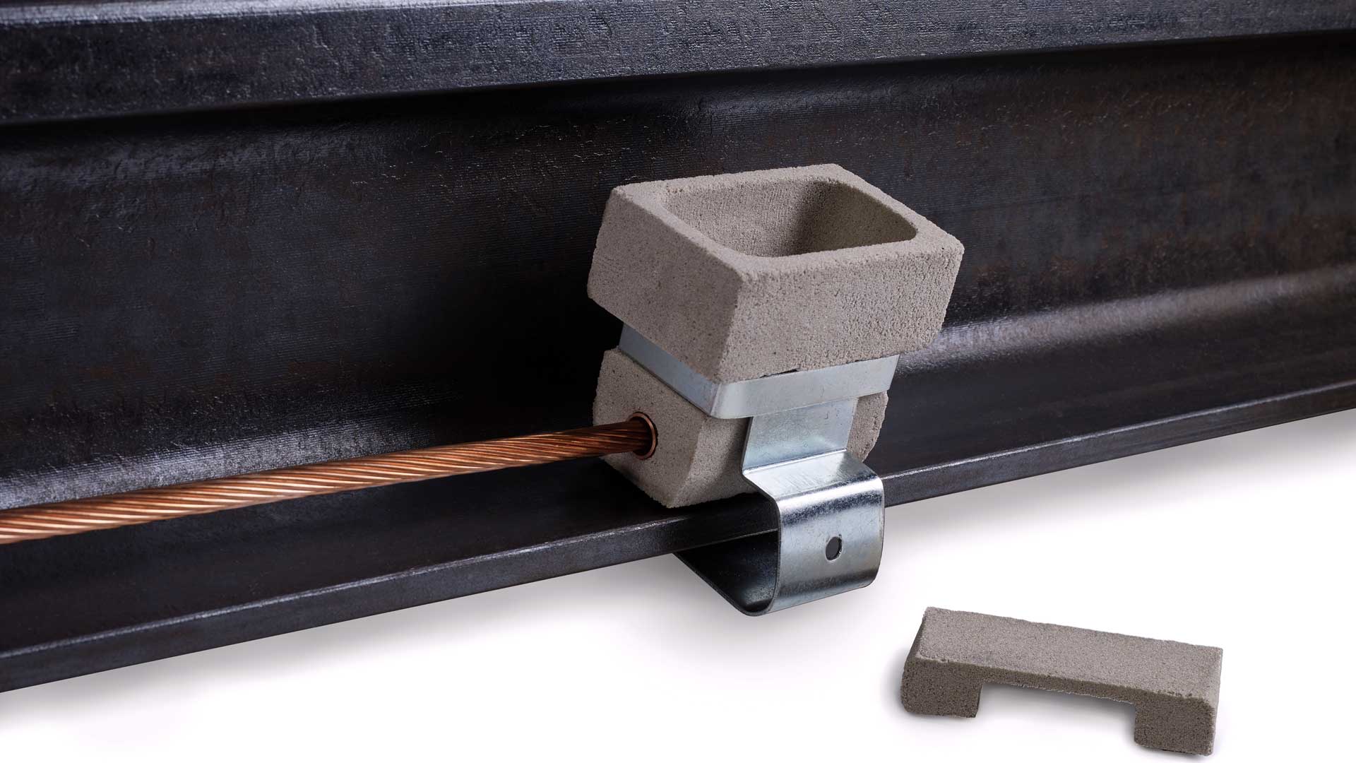
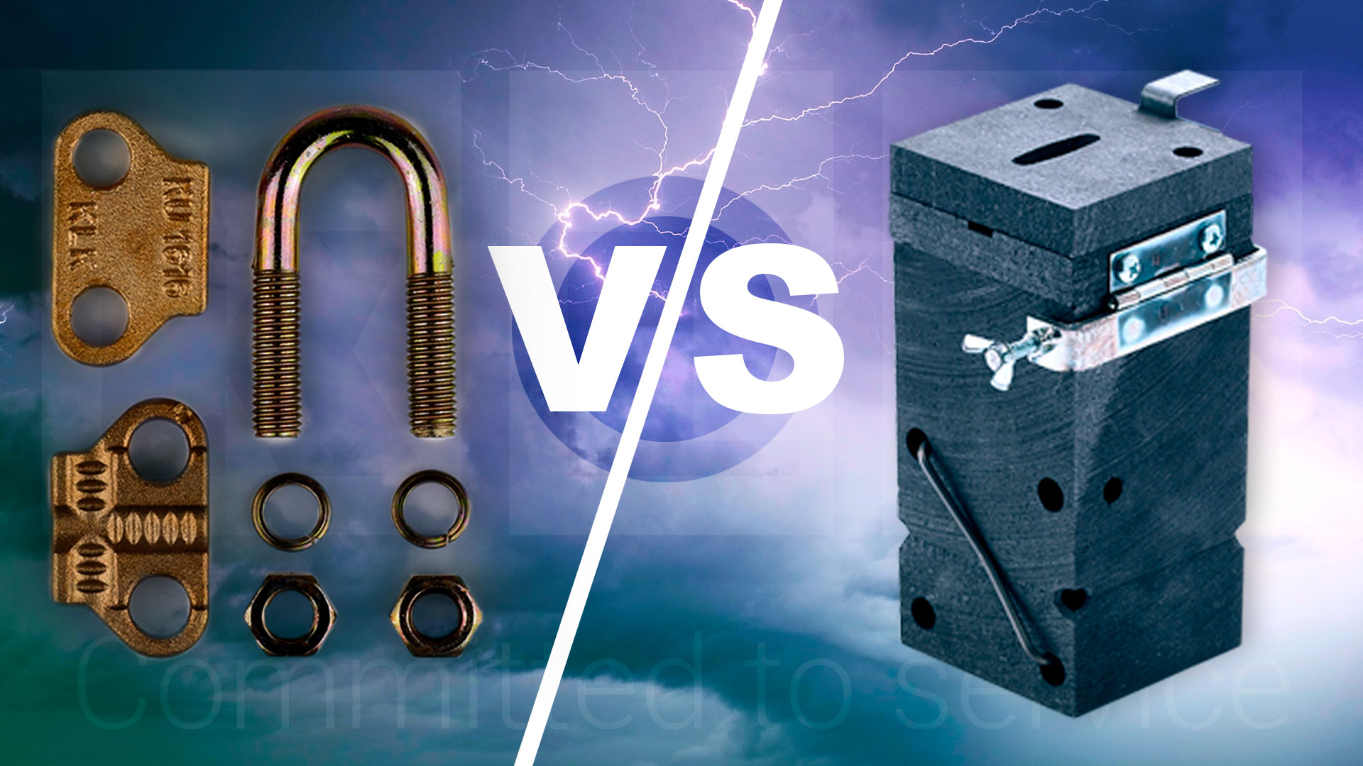
- Connections and Joints: Connections must be robust and low resistance, using techniques such as exothermic welding to ensure durability and good electrical contact, or traditional mechanical connections (ground clamps). Differences between connections here.
- System Configuration: The arrangement of components, such as in a grid or ring, should maximize the system’s effectiveness. Chemical additives can improve contact in difficult soils.
- Maintenance Considerations: A well-thought-out design facilitates maintenance and periodic inspections, allowing for resistance measurement without altering the installation. Access to connections through the installation of pits and inspection points will enable quick periodic maintenance and ensure that the installation maintains optimal values.
Resistance Calculation:
The system’s resistance must be low enough to allow for the effective dissipation of fault current, minimizing risks to people and equipment. Therefore, we need to perform a theoretical calculation followed by a field measurement using measuring equipment (Tellurometer).
- Formulas for Resistance Calculation: To calculate the grounding resistance, formulas are applied that consider soil resistivity, system geometry, and the materials used. Here, we must keep in mind all the previously mentioned values—soil resistivity, electrode length and diameter (ground rod), etc.—as this calculation is essential to ensure that the resistance is within acceptable limits.
- Ground Resistance Measurement with a Tellurometer: After the theoretical calculation, it is necessary to measure the actual resistance using a tellurometer. This device measures ground resistance using the three-point method, where current and voltage are applied to calculate the system’s effective resistance. Measurements should be taken under different conditions to obtain an accurate value. The goal is for the measured resistance to generally be below 10 ohms for low-voltage installations. If the values are high, it may be necessary to adjust the design, improve soil conditions, or both, to facilitate an easy path to ground for the leakage current.
Verification:
Verification is a stage to ensure the safety and effectiveness of the Grounding System in Electrical Installations. Through precise measurements, detailed inspections, and strict compliance with regulations, it is ensured that the system will reliably protect people and equipment, minimizing risks and ensuring safe operation over time.

Measurements | Grounding
Conclusion
Technology and materials used in grounding systems are constantly evolving. The latest innovations include new materials that offer greater durability and efficiency, as well as sustainable solutions that minimize environmental impact.
Grounding in Electrical Installations is a critical element in any electrical system, and its proper implementation is essential for ensuring both safety and efficiency. Using quality products is crucial to prevent system degradation.
At KLK Electro Materiales, we offer a wide range of solutions and pre/post-sales advice to help ensure that every element meets the most demanding regulations, providing durability and peace of mind in every installation you undertake. The choice of appropriate materials not only protects people and equipment but also ensures that the installation will remain safe and compliant with regulations over time.
More About Grounding

KLK Electro materiales slu
Mail | Web | Teléfono | Chatbot | Social Media
Need Help?