Protocol for Testing a Grounding Installation
Initial Visual Inspection
Key Actions in Visual Inspections at Grounding Installation Check in Single-Family
Before performing any measurement of the grounding resistance at Grounding Installation Check in Single-Family Homes Once you’ve confirmed that no part of the installation is energized, proceed to conduct a detailed visual inspection of all components of the grounding system, this step not only ensures that all parts are properly installed but also allows you to identify any visible issues that could compromise the safety and effectiveness of the installation.
A thorough visual inspection is essential to ensure the integrity and safety of the grounding installation, from cleaning connections to checking inspection pits and manholes.
A thorough visual inspection is essential to ensure the integrity and safety of the grounding installation, from cleaning connections to checking inspection pits and manholes.
Daniel Rendueles CMO KLK Electro materiales
Actions:
- Verification of Mechanical Connections: Start by inspecting all mechanical connections, such as clamps, rods, and plates. Ensure they are securely fastened and free from signs of corrosion, wear, or other damage. If you notice oxidation or dirt buildup, carefully clean the surface with a wire brush to ensure good electrical contact.
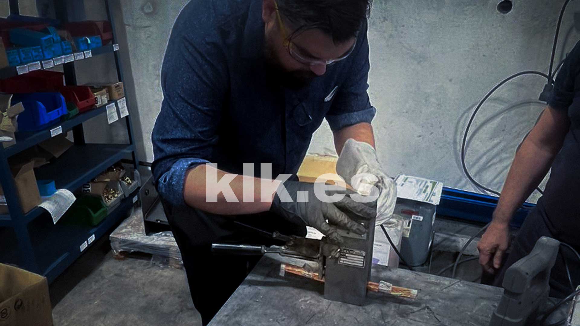
- Inspection of Exothermic Weld: Check connections made with exothermic welding for possible cracks or damage. These welds provide permanent, high-conductivity electrical connections so that any defects could compromise the integrity of the entire installation.
- Inspection of Grounding Pits and Manholes: It’s essential to inspect the pits and manholes where the ground connections are housed. These should be clean and free from water, mud, or debris that could affect the grounding connection. If you find any standing water, drain it and dry the area before continuing the inspection. Additionally, ensure that the manhole covers are well-sealed to prevent moisture or dirt from entering.
- Component Cleaning: During the inspection, cleaning the metal components with a specific cleaner is recommended to prevent oxidation and improve conductivity. Pay particular attention to joints and contact points where dirt accumulation can increase contact resistance, negatively affecting the performance of the grounding installation.
- Checking the Integrity of Conductors: Verify that the ground conductors are securely attached and free from visible damage, such as cuts, crushing, or degraded insulation. A damaged conductor can compromise the effectiveness of the installation and pose a risk to electrical safety.
Conducting a thorough visual inspection is an essential step to ensure that the grounding installation is in optimal condition before proceeding with technical measurements. This step is not only about ensuring a good connection but also about preventing future issues that could lead to safety failures.

Electrical professionals cutting off power before any work, wearing all required PPE | KLK Electro materials
Measuring Grounding Resistance
Ground resistance measurement, resistance meter, NEC regulations.
Measuring ground resistance is a crucial step to ensure that the grounding system functions effectively and safely. This process determines whether the electrical resistance of the grounding system is within the safe limits set by the relevant standards (e.g., NEC in the U.S.). Proper resistance ensures that, in the event of an electrical fault, the fault current is safely dissipated to the ground, protecting both people and equipment.
Tools and Procedure: Use a quality ground resistance meter and carefully follow the manufacturer’s instructions. It is essential to conduct the measurement under appropriate conditions, ideally on a dry day, to prevent soil moisture from skewing the results. Ensure the main ground connection is disconnected during the measurement to avoid interference and obtain accurate readings.
Measurement Points: Take measurements at several points within the installation, such as near the main ground rod and at the ends of the ground conductors. This will give you a comprehensive view of the resistance throughout the installation and help detect any variations that might indicate issues in specific segments.
Interpreting Results: The values obtained should be compared with the limits established by the relevant electrical standards. Generally, ground resistance should be less than 25 ohms for residential installations in the U.S., though lower resistance is preferable. If the values exceed the recommended level, corrective actions may be necessary, such as improving the grounding system or adding additional components to reduce resistance, like soil enhancers or chemical ground rods.

Equipment for Grounding Testing | KLK Electro Materiales
Analysis and Documentation of Results
Results analysis, documentation, NEC regulations.
Once the ground resistance measurement results are obtained, it’s essential to analyze them carefully, comparing them with the reference values established by the relevant standards (e.g., NEC in the U.S.). This comparison will help you evaluate the effectiveness of the installation and determine if it meets safety requirements.
Interpreting Results:
- Acceptable Results: If the resistance values obtained are below 25 ohms, the installation is generally considered safe for a single-family home. This indicates that the grounding system is functioning correctly, allowing proper current dissipation in the event of an electrical fault.
- Examples of Non-Compliant Results: If you find values above 25 ohms during the measurement, this indicates that the installation may not be providing adequate protection. For example, if you obtain a value of 50 ohms or more, it could indicate a poor connection, oxidation at the contact points, or that the ground rod is not deep enough or in contact with adequately conductive soil.
Visual Inspection Analysis: During the visual inspection, you may also identify issues affecting the effectiveness of the grounding system. For example, if you notice that mechanical connections, such as clamps or plates, are corroded or loose, this could contribute to elevated resistance. Similarly, the presence of moisture or debris in the inspection pits and manholes could indicate maintenance issues that need to be addressed.
Documentation and Corrective Actions:
- Documenting Anomalies: Record any anomalies found in detail, both in the measurement results and the visual inspection. This includes resistance values outside the acceptable ranges and observations of damage or deterioration in the components.
- Planning Corrections: Based on this analysis, plan and prioritize the necessary corrections. For example, if high resistance values are identified, consider replacing or reinforcing the ground rods, improving mechanical connections, or adding more rods to reduce the overall resistance.
Follow-Up: Conduct a follow-up after the corrections to ensure that the measures taken have been effective and that the new resistance values are within safe parameters. This not only ensures compliance with standards but also protects the occupants from potential electrical hazards.

Data Analysis of Grounding Measurements | KLK Electro Materiales
Maintenance and Recommendations for Grounding Installation
Regular maintenance is essential
Regular maintenance is crucial to ensure that the grounding installation continues to operate safely and efficiently over time. This process involves not only regular inspections but also the use of products and components that meet the strictest quality standards.
“Regular maintenance and the use of high-quality components are essential to ensure that the grounding installation operates safely and efficiently over time.”
Magali Pañeda, Commercial Manager Iberia | KLK Electro Materials
Maintenance Tips:
- Periodic Inspections: If during inspections you observe that any components show signs of wear, such as corrosion or material loss, replace them immediately. Using approved and high-quality products not only extends the installation’s lifespan but also ensures that ground resistance remains at safe levels.
- Replacement of Damaged Components: If during inspections you observe that any components show signs of wear, such as corrosion or material loss, replace them immediately. Using approved and high-quality products not only extends the installation’s lifespan but also ensures that ground resistance remains at safe levels.
Importance of Quality Materials: Compliance with manufacturing standards and the minimum coatings specified by regulations is essential to maintain the integrity of the installation. Components that comply with these standards not only offer greater durability but also ensure a safer and more effective connection. In this context, it’s important to note that using approved products, validated by the most important global quality standards, is a long-term investment in safety.


Conclusion Grounding Installation Check in Single-Family Homes
For example, KLK Electro Materiales products, designed and manufactured under strict quality standards, are built to withstand the most demanding conditions, ensuring a reliable and durable installation. Although it is not always directly mentioned, opting for higher quality components is a decision that significantly reduces the risk of failures in the grounding installation.
This focus on regular maintenance and choosing the right components ensures that the grounding installation in single-family homes meets the highest safety standards. By following these recommendations, you are not only protecting your home and its occupants but also ensuring that the installation functions optimally for many years.

Clamps in Production | Technician at KLK Asturias
More about Grounding by KLK


KLK Electro materiales slu
Mail | Web | Teléfono | Chatbot | Social Media
Needs any Help?